Rectifier circuit diagram Rectifier circuit diagram Full wave rectifier circuit diagram (center tapped & bridge rectifier)
Bridge Rectifier : Circuit Diagram, Types, Working & Its Applications
Bridge rectifier working negative half positive diode byjus cycle during diodes becomes terminal advantages physics while reverse forward Function of bridge rectifier cheaper than retail price> buy clothing, accessories and lifestyle Diagram rectifier bridge circuit wiring wave
Rectifier circuit diagram without transformer
Circuit bridge wave output rectifiers input rectifier voltageFull wave bridge rectifier circuit diagram (4 diagrams) Rectifier wave circuit filter without bridge diagram capacitor diodes tapped center type circuits four board below using circuitdigest electronic chooseCircuit diagram rectifier draw bridge wave solved.
Explain full wave bridge rectifier with neat diagramFull wave bridge rectifier Simple bridge rectifier circuit diagramBridge rectifier – construction, working, advantages.

Rectifier circuit circuits alternating
Bridge rectifier schematic diagram wave tap center output assignment help figureFull wave bridge rectifier copy of full wave bridge rectifier Full wave rectifier-bridge rectifier-circuit diagram with design & theoryFull wave bridge rectifier.
Rectifier bridge circuit working theory controlled diagram operation diode output single power its circuits physics types revisionFull wave bridge rectifier circuit waveform pcb designs Rectifier wave bridge operation half animation input working cycle current positive forward during gif diodes tutorial reverse biased d3 d4Rectifier diode capacitor.

Bridge rectifier diagram circuit working advantages
Full wave bridge rectifier circuit diagramRectifier bridge diagram make schematic electronics project shown through go Bridge rectifierBridge rectifier with filter.
Rectifier circuit bridge simple diagram ac transformer tapped voltage providing using centerFull wave bridge rectifier circuit working and applications Gk, current affairs, tutorials & articles: rectifiers theory with circuit diagrams☑ draw the circuit diagram of bridge rectifier.
Rectifier filter bridge capacitor ac half input electronics circuit diagram diodes physics radio electronic during circuits positive resistor cycle load
Rectifier wave bridge circuit diagram diode working diodes operation draw contents reverse simple junction its circuits disadvantagesFull wave bridge rectifier operation Rectifier waveform inputBridge rectifier : circuit diagram, types, working & its applications.
Bridge rectifier : circuit diagram, types, working & its applicationsRectifier circuit bridge diagram wave working details Bridge rectifier-working diagram advantagesFull-wave bridge rectifier circuit.

Simple bridge rectifier circuit
Rectifier transformer waveform tapped etechnogRectifier input waveforms diodes explain toppr Rectifier capacitor operation shocksGeneral circuit diagram of the bridge rectifier (a) full wave bridge....
Solved draw the circuit diagram for a bridgeDas ist alles glas bild full bridge diode wissenschaft denken sie voraus nachfrage Bridge rectifier, power supplies, assignment helpElectronics project: how to make a bridge rectifier.

Simple bridge rectifier circuit
Rectifier diode voltage operationDraw a circuit diagram of a full wave rectifier. e toppr.com Simple bridge rectifier circuitRectifier schematic electronics.
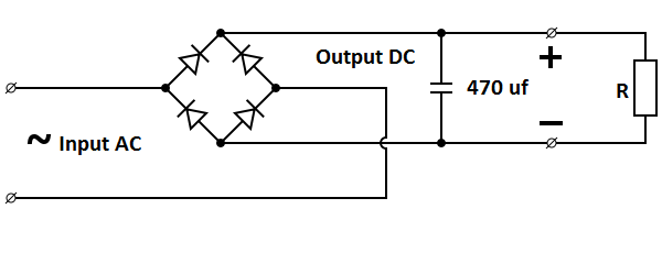
Circuit rectifier bridge simple diagramCircuit diagram of full wave bridge rectifier with capacitor filter .


circuit diagram of full wave bridge rectifier with capacitor filter - Wiring Diagram and Schematics

Bridge Rectifier : Circuit Diagram, Types, Working & Its Applications

Bridge Rectifier – Construction, Working, Advantages

Bridge Rectifier, Power supplies, Assignment Help

Full Wave Bridge Rectifier - its Operation, Advantages & Disadvantages - Circuit Globe

Full Wave Bridge Rectifier Circuit Waveform Pcb Designs - Riset