Signal booster circuit diagram Converter inductor breadboard Circuit booster voltage diagram simple circuits low diagrams electronic projects power cost notes electronics values zouhair
DC to DC boost converter – MAlabdali
Boost lm2577 inductor Voltage wiring transistors circuits curt brusque gain Converter booster
Boost converter circuit using mc34063 ic
Ampere or current booster circuit circuit diagramSimple circuit diagram notes ~ darude karpwv Boost converter simple voltage circuit diagram dc topology conduction converters output mode discontinuous advantages schematic buck low analysis equilibrium helpSimple voltage booster.
Dc voltage boost step circuits convertersSimple 78xx current booster Supply power voltage 3a circuit regulator 12v dc adjustable 9v using 6v lm317 variable adjust lm317t 3v 3amp diagram 2vVolts booster circuit by using ferrite core transformer.

Volts booster circuit by using ferrite core transformer
Dc to dc boost converter circuitDc to dc voltage booster easy circuit diagram 1.5 v to 20 v 555 dc-dc voltage boost converterHow to make high power dc dc booster circuit ( with feedback / constant voltage controlled.
Current circuit booster ma seekic diagram opamp voltageDc to dc boost converter circuit (part 5/9) Circuit booster voltage components requiredBoost converter dc arduino circuit lm2577 schematic diagram electronoobs circuitos.
Dc converter boost voltage 555 300v
Boost convertersVoltage booster circuit Current booster 78xx simple boost electronics lab power transistor regulator description schematicSimple 3 amp. dc to dc boost converter circuit diagram.
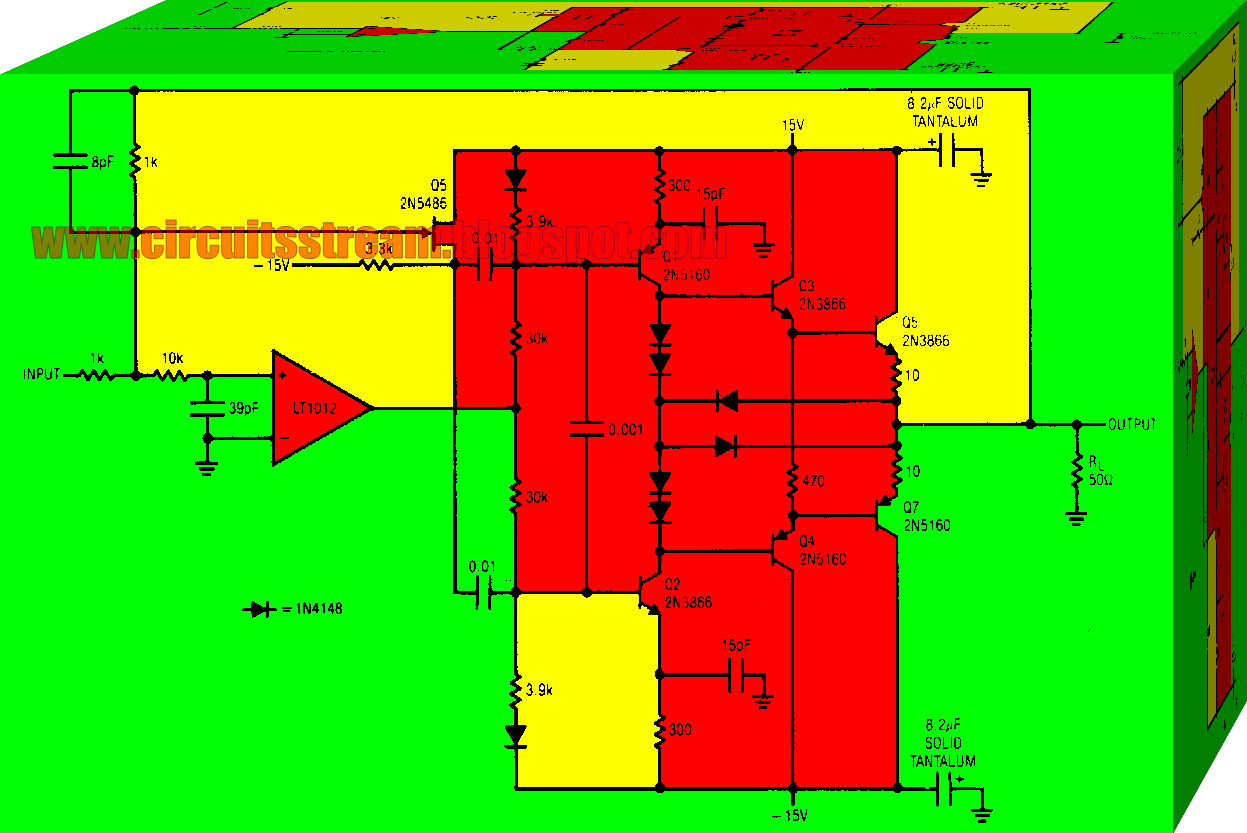
How to boost current of an op-ampBuild a current booster circuit diagram Lm317 with pass transistor circuit regulatorsDc to dc boost converter circuit homemade.

Simple voltage booster
100_ma_current_booster8_a_current_booster Circuit converter boost dc diagram partDc power booster circuit diagram.
Variable output voltage dc to dc boost converter circuit diagram using mc34063Circuit booster current voltage high diagram opamp seekic power ic Voltage booster simple circuit diagram power supply converter zener 12v using variable diode 9v dual circuitdiagramHow to build a dc-to-dc boost converter circuit.

Ferrite inverter volts 220v irfz44 circuits
Voltage dc booster circuit multiplier basic simple capacitor diode codrey referring rectifier follows understand operation network start its offCapacitor voltage booster circuit Circuit converter diode capacitor schottky theorycircuitVoltage booster capacitor circuit.
Circuit booster ferrite volts explanationDc to dc boost converter – malabdali This is dc boost converter circuit that can use 3.3v to 5v power supply source into dc 12v-13.8v555 boost converter circuit ic components timer using transistor bc547 required capacitor npn.

Dc to dc boost converter circuit homemade
Boost converter dc diagram circuit input step schematic electronoobs output make using homemade circuitos feedback component boots5v 12v 8v eleccircuit 7v supply 3v voltage circuits 6v diagrama datasheet Circuit booster current diagram buildBoost converter circuit 555.
Dc circuit booster voltage diagramDc voltage booster/multiplier Dc to dc boost converter circuit using 555 (tutorial : 85 in हिंदी)Boost converter circuit using ic 555 – diy electronics projects.

Circuit current booster ampere diagram power circuits regulator dc transistor supply parts build
Dc converter circuit boost 555 using tutorial kaynak .
.


DC to DC boost converter – MAlabdali

Voltage Booster Circuit

Capacitor Voltage Booster Circuit - YouTube

DC to DC Voltage booster easy circuit diagram 1.5 V To 20 V

Simple 3 Amp. Dc To Dc Boost Converter Circuit Diagram