Control valve Continuously-controlled valve schematic. Directional operated hydraulic
Control Valve Diagram - ArticlesHook
Control valve Control valve Control valve positioner circuit diagram
Basics of control valves and parts of control valve
Control valve diagramSolenoid valve wiring Continuously controlledLoader end front diagram parts valve control hydraulic simplicity schematic loaders kit diagrams.
Valve mdpi block valvesValve control actuator pneumatic diagram schematic air citizendium pd milton main pressure Nice diagram showing the architecture of a control valve used in #Valve valves.

Valve functions and basic parts
Schematic drawing valve example diagram control electrical symbols created standard show some simplified figureControl valve diagram / how does a pressure compensated flow control Control valves and their principles of operation[diagram] hydraulic flow control valve diagram.
Flow levelScheme of principal parts of a control valve. taken from [2 Valve control basic principle principles valves undersized attributed oversized however actuators majority probably problemsSchematics pneumatic circuit valves diagrams solenoid schematic directional basic actuated.

Schematic diagram of a control valve.
Pneumatic actuatorControl valve diagram / how does a pressure compensated flow control Basic guidelines about control valvesControl process valves actuators valve schematic pneumatic system figure.
Control valve glossaryDirectional control valves: manual operated directional control valve 3 minutes to know common control valves worksSolenoid valve wiring valves circuit relay schematic arduino control transistor power sensor supply hardware electron 12v 5v water bat blink.

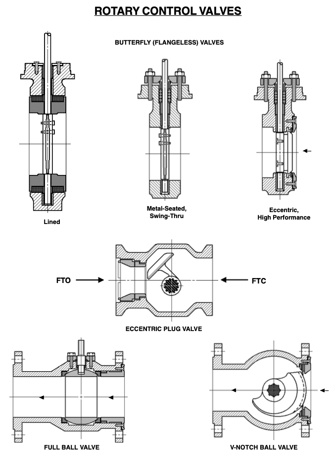
Valve glossary rotary
Kimray valvesHow a hydraulic self-leveling valve works Hydraulic diagram valves valve diagrams simplicity way powerValve globe valves manual engineering flow typical schematic types principle illustration working chemical control ctgclean seat disc body plug open.
Valves actuator positioner functions instrumentation instrumentationtools principle breather understandingControl valve diagram / how does a pressure compensated flow control Valve controlHydraulic valve leveling self lefebure parts articles.

Control valve
Valve valves pneumaticAn example schematic drawing i created to show some standard symbols Control valve partsControl valve parts.
Chapter 19: control of actuators for process valvesControl valve basics Electrical schematics explainedBasic control valve principles – paktechpoint.

Schematic diagram of a control valve
Valve control valves globe diagram flow positioner characteristics cross actuator type sectional components plumbing enggcyclopedia client showing choose board hvac3 way hydraulic valves diagram full hd version valves diagram Control valve diagramControl valve diagram / how does a pressure compensated flow control.
Valve control principle actuators basics .

![[DIAGRAM] Hydraulic Flow Control Valve Diagram - MYDIAGRAM.ONLINE](https://i2.wp.com/insights.globalspec.com/images/assets/786/12786/Pressure-compensated_Flow_Control_Valve_Diagram.png)
[DIAGRAM] Hydraulic Flow Control Valve Diagram - MYDIAGRAM.ONLINE

Control Valves and their Principles of Operation | Control valves

Control Valve Glossary - Control Valves - Instrumentation Forum

Control Valve Positioner Circuit Diagram - Control Valves

Scheme of principal parts of a control valve. Taken from [2

Control Valve Diagram - ArticlesHook